In case you've missed it: A new graphics card for the PCMCIA slot is soon to be released.
The original information seems to date back to the Amiga 40 event in Germany, and was amplified by Amiga Bill when he put it on his YouTube channel in Oct. 2025, but some updates have been coming in over the past few weeks.
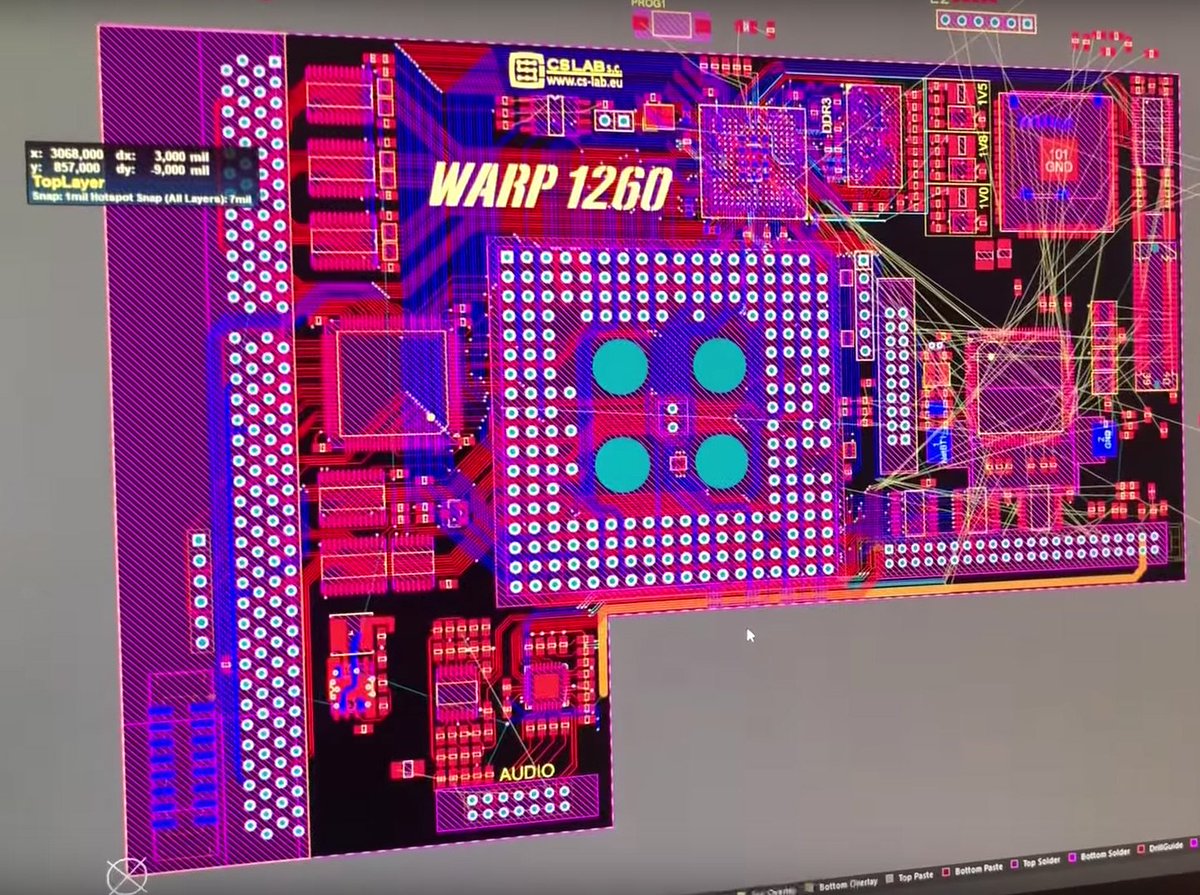
Some information has been published on various websites (see links below), and in an interview in "WhatIFF?" magazine Issue 5.19 (April 2026) (see links below), Oliver gives a couple more details about the design. The P-Vision is a PCMCIA device, thus it works with an Amiga 600 or 1200. A 68020 CPU and some FastMEM is required, though. It's a RTG graphics card with HDMI output, providing up to FullHD graphics resolution in 32-bit, equipped with a 64-bit blitter capable of ~320M pixels/s. The driver for P96 (Picasso96) RTG system is developed by Thomas Richter. ("...smooth, buttery screen dragging..." - O. Achten, "WhatIFF?")
Some of the specifications seem to be preliminary, full details are planned to be revealed at ARC #4. (Based on the information currently available it's not entirely clear what sort of sound support the device might have.)
It will be distributed by Alinea Computer (amiga-shop.net), but it's an open-hardware project aiming for affordability and simplicity of design, which means you can also build one yourself. The information required to do so is planned to be released after some months of commercial sales. The cost of building one is estimated at around 100 EUR.
Great stuff! The PCMCIA slot is the best i/o port the Amiga ever had, and it needs more love than just a CompactFlash card adapter. P-Vision certainly makes great use of the PCMCIA slot, and is an outstanding addition to the sadly very short list of Amiga PCMCIA devices.
As a sidenote: In the "WhatIFF?" interview, Oliver also reveals that he is working on "AmiGUS mini" soundcard for PCMCIA, and "Demon 1260" 68060 accelerator for Amiga 1200, among some other things.
Astronauts of the International Space Station can plug in an Amiga 600, 1200, or CD32 and play games on a beamer!
A beamer with composite video input aboard the ISS
15.6kHz analog-video compatible displays are a bit of a rarity these days, but of course the ISS, being the pinnacle of human achievement, has one, with a composite video input. It is very unlikely, though, that Amiga hardware is available in space.
;-)
(Picture: Arrival of additional/rotating crew at the ISS, March 2025)
A surprisingly simple repair to a microscopic, but essential problem with an Amiga 1200's floppy drive.
This drive didn't work reliably, and at some point failed completely, not detecting disk media anymore. Only with a little bit of extra pushing on the disk, it would click and start reading, but immediately stop when released. A more thorough inspection was required.
The mechanism didn't feel very snappy when inserting the disk, so some dirt, lack of lubrication, or worn out spring was the first guess. But it turned out everything moves nicely. Next, the "disk inserted" switch was inspected, drenched in isopropyl alcohol, tested, even resoldered, it was fine, but the drive still didn't work. Suspecting a worn out disk "sledge", that prevents the switch from getting fully pressed down, a little bending was applied to some of the metal side pieces - with no success.
Amiga 1200 floppy drive without cover plate - the slightest touch would make it work.
Basically everything about this floppy drive was fine, only it still required some pressure on the top of the disk. With more inspection, cleaning, etc. it became a little bizarre: Only minimum pressure was required, the weight of a finger, creating microscopic movement.
The solution was found when looking at another, very similar floppy drive: The disk guides at the drive's front aren't supposed to be tilted to the inside. On the other drive, they're perfectly horizontal, parallel to the top edge.
That was a little unexpected. Amiga computers are old, this Amiga 1200's drive had the guides slightly bent, tilted towards the inside, for decades, and worked fine. But it makes sense, bent guides could prevent the disk "sledge" from fully touching down on the drive's base plate, thus not triggering the disk detection signal properly.
Bending the guides back to a (near) perfect horizontal position indeed fixed the problem.
Open drive, and disk "sledge" (top part), with straightened guides at the front. A similar drive, used for comparison, on the left.
The lesson learned is that these guides wear out, and they were worn out on this drive. Who would've thought. They seem to hang in the air when no disk is inserted, and they're hard to see when a disk is in the drive. If you've never consciously looked at them, or even if you have, you assume they're built this way. And you probably don't expect that when they're bent down another 10th of a millimeter, they prevent the drive from working.
It might have worked for decades, and it wasn't even expected to be wrong, but still: If it's bent, it's probably broken!
Missing screw on the backside - that's acceptable.
While at it, the casing of the drive was checked, so the sledge has no unnecessary action. This drive is missing a screw on the backside, but with a little straightening (bending... ;-) ) of the top piece, and making sure its sides fully snap into place on the drive's body, a tight fit can still be achieved.
Floppy drive immediately detects floppy disk again. Very good.
That was a very unexpectedly simple repair. The drive disassembly was unnecessary, it probably could've been done even without opening the Amiga computer. And it even was totally analog. Awesome.
Over the last decades I've tried countless different setups in order to properly capture the Amiga's video output. Pretty much all of them were unsatisfactory, or just way too expensive (think A4000 plus V-Lab Motion or PAR). Old PC analogue capture cards give quite good results, but device drivers and PCI slots for these are getting really rare. So - finally! - I've decided to drop my attempts with the Composite video connection, and build an S-Video adapter for the Amiga.
Composite video merges all video information into one wire, so its signal quality is somehow limited by design. Composite video is easily available on all Amigas (built-in, or via A520 TV Modulator), but the real disappointment happens when you see this signal recorded with some average digitizing equipment. Weak colors, red all over the place, blurred, misaligned - the results are hardly enjoyable.
The Amiga provides separate red/green/blue component signals on its DSUB23 video output, which many people (including me) use with a RGB-to-SCART cable. Such a cable gives great picture quality, but only if the receiving device a) has a SCART input connector, and b) uses the separate color components.
Among my video capturing attempts was a Terratec USB box with a SCART connector, which looked great from the outside. But it turned out it doesn't use color components, only the Composite signal provided on one of the other SCART connector pins. Blurred, washed out, ...again. Sigh.
S-Video, aka Y/C, uses two wires: brightness (Y, gamma, luma, luminance), and color (C, chroma, chrominance). That doesn't sound like much on first sight (hear), but S-VHS tape recorders featuring S-Video were super expensive back in the day, and most modern analog video capture devices, including the cheap ones, have a S-Video input. So at least some improvement of picture quality can be expected just from the different specifications, and maybe from a different signal path inside the capture device.
The design of the circuit looks straightforward, it uses a AD724 video chip, and it adds another Composite video output which may come in handy some day. Nice, let's start building!
The DSUB23 video connector was created from a DSUB25 one, and the SMD video encoder chip needs a little "daughterboard" adding "human-readable" soldering pads (holes).
Test-ready build of S-Video adapter
Oops, something went wrong...
First testrun: There's clearly something wrong here. This is what you get when you use a PAL crystal (4.433619MHz), but still have the AD724 set to NTSC output by connecting +5V to STND (pin 1), as shown in the (NTSC) schematics. To switch the chip to PAL video mode, STND must be connected to ground. (As noted in the bottom section / "2017-04-03 UPDATE" of the article at Everything Amiga.)
Slightly better soldering, and added composite video out
It took me a couple of attempts to get a working "daughterboard" with the AD724. Maybe the small green PCBs are of inferior quality. Or maybe just my soldering skills are, and I fried something a little too long.
Here are some pictures of the results, with RGB-to-SCART and Amiga 1200's built-in composite video for comparison.
RGB-to-SCART
A1200 built-in Composite
Composite (via S-Video adapter)
S-Video, Hi-Res 640x256
S-Video, Hi-Res laced 640x512
S-Video, Super Hi-Res laced 1280x512
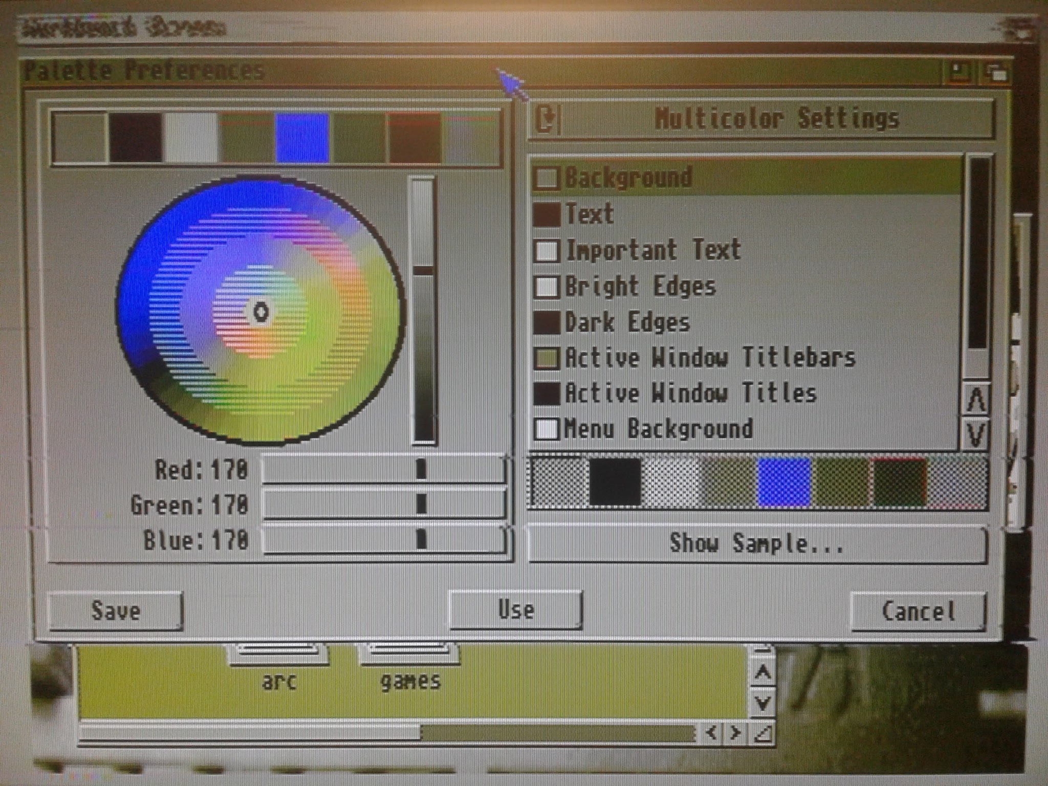
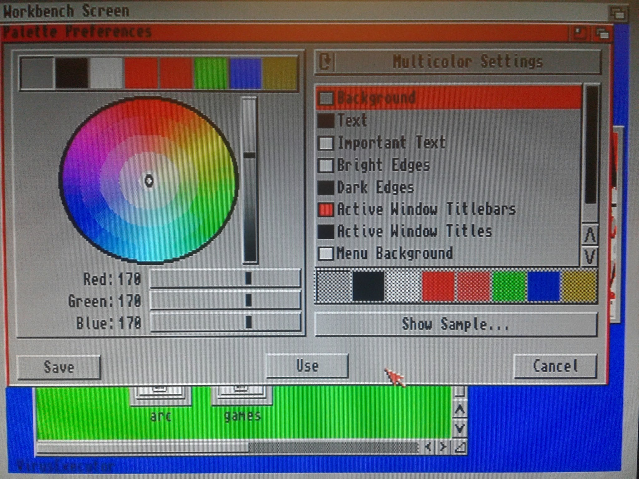
Wow, it's pretty much as good as RGB-to-SCART! I certainly didn't expect that much of an improvement. (And I never knew "Palette" prefs shows up in different shapes depending on screen size. Nice.)
A very cheap USB video capture device
And here's a frame of S-Video captured with a 15EUR USB dongle capture device:
Screenshot of Amiga S-Video capture on Linux computer
Wow, that's... pretty good! Ohyeah, I can use that! :-D
To give the thing some protection, esp. when plugging/unplugging it, a simple housing was quickly created. It's a bit flimsy, and not particularly beautiful, but it'll do for now.
With this successful proof-of-concept I'll probably build another adapter, with better layout, less wires, and a sturdy, more precise case. Also maybe some shielding will further improve picture quality.
Current "final" build state, with "modular" video chip board
Awesome! It works, is usable, and I'm totally surprised by the amazing capture quality. I expected either total failure, or a just a slight improvement, due to cheap, inferior capture device. But it turns out S-Video makes all the difference, two wires are obviously far superior to just one.
On July 17th 2022, Beth Richard, lead engineer of the CD1200 in 1993/1994, visited the Retro Computer Museum in Leicester, UK, making more history and providing invaluable information by talking about her experience, and actually taking the device apart.
A video of the event was uploaded to YouTube about a month ago.
Here's the video of Beth Richard taking the (presumably) only Amiga CD1200 in existence apart (on YouTube channel "PixelFix"):
https://www.youtube.com/watch?v=GYGhOuIysVU
Shortly after the video was uploaded to YouTube, Ms. Richard left a comment which provides even more insight into the background of the CD1200 (transcript of comment follows).
Ms. Richard's comment on the above video (source: https://www.youtube.com/watch?v=GYGhOuIysVU)
"That was quite an experience! I'm so glad we got to do that.
People look back at my work and assume that as the lead engineer, I was somehow a Commodore "Legend". I'll leave that to those to whom it really applies. I was a junior engineer at the time, near the beginning of my career. I think the best way I can describe how I ended up being the lead engineer on this project is a quote taken from Any Weir's "The Martian": "Ares 3. Well, that was my mission. Okay, not mine per se. Commander Lewi was in charge. I was the lowest ranked member of the crew. I would only be 'in command' of the mission if I were the only remaining person.What do you know? I'm in command."It was very clear by the time I started this project that the end was near. I worked on this at a time where we thought it may be possible that someone would buy the company and take it seriously. Having demonstrated that there were ideas and projects with a roadmap into the future would be what someone would want to buy. Several of us were working right to the end to keep a portfolio of projects that could be turned on immediately, should a new owner wish it. (Like the work Dave Haynie was doing at the high end, and some stuff Greg Berlin had been doing too.). It was not to be.
I'm so embarrassed about misspeaking that the date of Pearl Harbor was 7-Dec-1943... ***1941***!!!! I know that! How could my mind have been so bounced and distracted that I would have gotten that wrong? I might have had an excess of adrenaline at the time.
Although I designed that in 1993-1994, I was particularly nervous about opening it because it isn't mine... it's the RCM's. And it's got to be the only example left in the world by this point. I offered to coach Andy through opening it as it's his museum's property, but he wouldn't have it. Sadly, in order to make it work, it needs the controller board to go into the A1200 and cable that came through the port on the rear of the A1200 to connect it to the drive. None of those seem to have survived.
I know it was edited for privacy reasons, but when I was going through the names I saw on the PCB, I started with the first one on the list... mine. The names were actually the userIDs for our email addresses, each of which ended with @ 'cbmvax.commodore.com'. And the word preceding that cut was my userID: brichard. Since that email has been invalid since April 1994, I'm not terribly worried about people knowing it.
And credit where credit is due: My spouse, Teresa, who has her degree in Engineering Management that included nearly the complete curriculum of Mechanical Engineering took a look at the lid spring and noticed the extra bend that was causing it to pop out of position. When she showed it to me, I recognized that the spring was not actually the original factory spring. It must have been broken at some point and someone replaced it by bending a bit of spring-steel wire to (nearly) match. In fact, that mechanism was not custom to the CD1200 - it was re-used from the CD32. So by comparing with a CD32 lid spring mechanism, we confirmed it was wrong and replaced the spring with one from a CD32. The lid works correctly again!
Such a great day! Thank to Andy for inviting me to the RCM and being so gracious about the experience."
(transcript of@bethteresarichard3910's comment on https://www.youtube.com/watch?v=GYGhOuIysVU)
Great work by Ms. Richard, Retro Computer Museum, and all others involved! Thanks for sharing, and keeping the CD1200 alive.
Actually I don't like the Competition Pro joysticks too much. A kind-of review.
I think the Competition Pro puts unnecessary strain on your wrist, and has some other disadvantages.
Classic red-black color scheme Competition Pro joystick
You'd probably intuitively grab the Competition Pro's stick more or less from above. That position, plus the height of the body, the placement of the fire buttons, that'll make you put your thumb towards the edge of the top casing instead of across (unless you use the fire button on the opposite side), and the small footprint area of the bottom casing, makes the entire construction work kind of like a lever, twisting your wrists in opposite directions. Depending on the individual specimen of Competition Pro joystick, the spring and microswitches involved with stick movement / directions might be pretty strong, requiring unnecessary force, potentially increasing wrist strain. In addition to the sub-optimal way the (probably left) fire-button-hand is placed regarding overall grip and stability, pushing down the button creates an unnatural motion of the stretched out thumb more towards the index finger than towards the center of an imaginary Tennis ball in your hand, quickly exhausting the thumb's muscles. If the fire buttons slightly tilt, and cant, which they occasionally do, exhaustion is even quicker.
And then, while most microswitches are great, they're also sometimes pretty loud, esp. when put into a bulgy casing like the Competition Pro's. Depending on the situation the clicking of the switches can get a little annoying.
I prefer Quickshot I's, which you'd typically grab more or less horizontally, thus typically applying some downward force. Combined with a much wider footprint area, overall lower-profile body, the (body) fire button positioned less close to the body's edges, and suction cups on the bottom, the Quickshot stands much more firmly, esp. on hard, plain surfaces. It's pretty usable even with one hand only.
A 30 year old, heavily used SVI Quickshot I - is it better than a Competition Pro?
The Quickshot I doesn't have microswitches, but you can easily service its open tin switches, and they're hardly audible when in use. The stick wears out over time, reducing force required. With a stick moving that smoothly, you can put your steering hand's fingers near the lower end of the stick, creating super fast changes in direction, and almost eliminating wrist strain from both hands.
Of course the Competition Pro is still a great product. It has a lot of advantages - its die-hard construction and build quality, iconic looks, comfortable ball-stick, and more. Many people got used to it, and rightfully love it.
Certainly not everyone will agree with the above analysis of the Competition Pro's construction and handling. And to be honest it's not 110% serious - it's based on very little test data, and heavily biased. ;-)
But one day it just had to be said: The Competition Pro isn't necessarily the best, or the only usable joystick in the world. This is just an example where personal experience differs from widespread opinion. Why not try a different joystick? Computec has some not-so-fancy-looking, but really well-working models. Quickshot I and II are great microswitch-less designs. And there are many others.
Computec Quick Gun Turbo Pro - a great Competition Pro alternative
Awesome news from the hardware scene: After numerous FPGA Amiga implementations, re-imagined Amiga 500 and 1200 mainboards, all sorts of new accelerator designs, and so on, the Amiga 1000 gets a major overhaul with "AMIGA A1100".
Miguel "Estrayk" Fides from Spain has just published information about his "A1100" mainboard, which is designed to fit a Amiga 1000 case. Using modern components along with some original ones, this new mainboard looks quite different from the original Amiga 1000 PCB - and it has a lot of impressive new features:
CPU Motorola 68020@14Mhz (PGA)
OCS/ECS chipset (original Paula / Agnus / Denise required)
2MB ChipRAM
64MB FastRAM
2.5'' IDE controller
support for single and dual Kickstart ROMs (three sockets total)
built-in flickerfixer and scandoubler with RGB, cinch and VGA connectors
A1000 (86pin) and A1200 (150pin) expansion connectors
A1200 clockport
ATX power supply connector
According to SysInfo the A1100 is easily twice as fast as a stock Amiga 1200.
It looks as if currently there's no distribution or anything planned, but that doesn't mean it won't happen, the developer is evaluating possible options.
Here's a video showing the A1100 in action (2021-02-10):
https://www.youtube.com/watch?v=cP2rrnZsDm8
Very nice, certainly a great piece of Amiga hardware to keep an eye on!
My "Frankenstein" Apollo 1240 accelerator needed some decent cooling, so I built something.
The ACT Apollo 1240 is a great accelerator for the A1200, but it requires some extra care. Among the quirks and issues owners of an Amiga 1200 with 68040 or 68060 accelerator have to deal with is heat, especially when using higher- or overclocked CPUs, in a desktop computer case, and when there's no manufacturer supplied cooling mechanism available. The 68040 CPU present on this specimen of the ACT Apollo, with a 80Mhz oscillator, gets unpleasantly hot, so it is likely to become unstable, wear out, and/or damage other components.
To provide some improved cooling to the CPU, a second heatsink was added next to the first one, where previously a 30x30x7mm fan had been positioned. The fan would now require a case and air duct that fits the Apollo 1240 plus a potential 3.3V voltage converter for potential 68060 upgrade, inside the Amiga 1200 desktop case, and direct air towards the CPU and heatsinks in a reasonable way.
Blender 3d modeling fan case
Using Blender I created a 3d model, printed it, refined it, and re-printed it.
(Current) final version in the center
The 3rd incarnation of the model is the (current) final result. The fan more or less rests on three legs inside the case, and has been glued into place with hot glue, sealing off gaps. The case is 3d-printed from PLA at 0.1mm layer height, with spacer sockets on the bottom to leave room for solder and solder pads below, and glued to the Apollo PCB, also using hot glue.
New cooling system with fan, case and heatsinks
First test runs have shown:
a) The cooling effect seems to be pretty strong! From the previous installation with a CPU temperature that's painful to touch ("ouch! burns!"), it went to somewhere hot that still allows sustained finger contact to CPU or heatsink. Certainly a huge improvement.
b) The noise level is easily tolerable. The fan motor is quite audible at times, but there's comparably little hissing from the air moving through the plastic case. Maybe this can
be improved further with a more elaborate shape of the case / air duct.
c) Hot glue is awful because it's somehow neither fish nor flesh, but it's easily removable and makes a very good seal for small gaps in plastic parts. The Apollo 1240 has very few features for extra parts to be be attached to, the CPU might get too hot for direct contact with PLA. Applying and removing hot glue worked very well - at least for development.
b) Overall height, and some space restrictions, are at the borderline. An extra millimeter here and there would be nice - maybe a little cutting and scratching will do, or it's just Amiga case inconsistencies. Otherwise the fan case 3d model might need some modification.
It kind of looks like a mech...
Room has been left for the 68060 voltage converter, but a SCSI connector or second SIMM socket probably won't fit anymore.
One of the heatsinks was already there, so the other one got cut for the 68060 voltage converter "jumpers", red (left of CPU) and white wires are repairs by previous owner
I'll see how the PLA takes the temperature, and if the system remains stable in the long term and under heavy use. Also time will show if hitting the Amiga's keyboard above the cooling system and Apollo board will affect the installation. I guess with lots of warm air around, the new fan case will deform if there's mechanical pressure from one of the other computer components applied to it.
For now I consider it a success, entering "real-life" testing stage - 68040 power at 40Mhz, plus there's a chance this new cooling system will allow a 68060 to be installed on the board. :-)
You might have seen our little article, asking for support for APECAT, the "Amiga Processor Expansion Card for Application Transfer" - we have good news!
In case you haven't heard about APECAT before: Stian Søreng is developing a homegrown expansion device for the Amiga 500 (MC68000 CPU slot - probably Amiga 2000, too) that is designed to be able to directly upload code to the Amiga's memory, and execute it on boot.
Pretty cool, isn't it?
Stian has just reported via facebook that he's making progress, his prior problems seem to have been solved. In a new article on his website (see link below) published on Aug. 31st, he describes he had to fix timing issues both in hard- and software, and has started working on revision 2 of the APECAT.
He also created a short video showing his strikingly simple and simply amazing invention doing a little work! Here it is:
The name "VARTA" strikes fear into the hearts of Amiga 500 plus, and A501 memory expansion owners: VARTA rechargeable batteries have been built into these devices, and with growing age are prone to leak green acid, damaging the printed circuit boards and other components.
Original rechargeable battery from an A501 memory expansion
So it's an absolute requirement to remove that rechargeable battery, and clean the PCB from all acid that might have spilled out, if you want to keep your device intact. Most Amigans seem to use vinegar and alcohol for cleaning, sometimes using a tooth-brush to rub off any damaged material. If you don't catch the "infection" in time, traces or components might be damaged, requiring repairs.
But still it would be nice to have a working backup battery installed to your machine. Coin-cells, type CR2032, are a good replacement, they're widely available, and do not leak. But keep in mind that these aren't rechargeable - the Amiga provides recharge-current to it's batteries, so when replacing the original rechargeable one, we need to take care of that to avoid (additional) damage.
Removing the rechargeable VARTA battery shouldn't be a problem, you just need a soldering iron. Next is the cleaning - and if you're unlucky - repair job.
When you're done so far you can install you coin-cell. The original VARTA batteries are 3.6V. CR2032 coin-cells are 3V, that's within range for the clock chips used in Amiga 500 pluses and A501 memory expansions (mostly OKI M6242 chips).
With some googling I found Daniel Schneller's nice article on how to do the replacement. He's done what's required, and added a few details, mainly putting the new battery on a separate board to avoid stress to the original PCB when exchanging the coin-cell in the future - an idea I like very much. I basically did the same, but wanted to keep my A501 in "one-piece", so I decided to put the extra board onto the A501 itself. According to one CR2032 manufacturer's docs, a diode and a 200 ohms (minimum) resistor are required to keep the Amiga's recharge-current away from the new, non-rechargeable battery. I'm using a 220 ohms resistor, just for a little bit of extra-safety.
Here's a schematic of the new battery board:
Battery board schematic (click to enlarge)
Nothing spectacular - have a piece of drilled board ready, the components as shown in the schematic, add a coin-cell holder, wires, and pin headers, and basically all that's left is the soldering.
New coin-cell battery on a separate drilled board
To fix the new board to my A501 I added several layers of duct-tape to the bottom side for padding, and a small piece of extra-strong double sided sticky tape as a (hopefully) removable glue.
The extra board is held in place by double-sided sticky tape
I'm quite pleased with the result! It doesn't look totally amateurish, there's close to zero modification to the original PCB, the sticky tape should keep the new board properly in place - and if I should ever want to do so, I could probably revert the modification completely.
And best of all: it works. :-) Thank you very much, Daniel Schneller, for sharing your know-how and experience!
An interesting little project by Norwegian developer Stian Søreng, the APECAT - short for "Amiga Processor Expansion Card for Application Transfer" - aims to enable you to upload data directly to your Amiga's memory.
The APECAT - a successor of the "68k Sandwich" (see "Sources" below) - is quite a simple circuit board, using an ATmega128 controller, that sits between the Amiga 500's mainboard and the MC68000 CPU. Being able to use a PC computer and this board to "inject" software directly to the Amiga's RAM would hugely simplify a software developer's work, and also has a lot of potential for retro gamers.
BUT! It doesn't work yet. So far things look promising, but there are still a few issues to iron out - so Stian Søreng asks for YOUR help!
If you're an Amiga hardware / assembler guru maybe you can contribute?
The arrival of CD-technology for personal computers caused a huge shift in software development and user experience. The added storage capacity led to a hugely increased amount of content delivered with a software title. Gone were the days of swapping floppy disks, now a single CD could deliver everything required, and much more. CD was everything and everywhere.
Commodore's CDTV, with a built-in CD-ROM drive, was an early attempt, but the underlying original Amiga hardware wouldn't benefit too much from a CD drive, and there was simply not much experience in how to make good use of the CD's extra capabilities. But after the PC and Apple Macintosh market had established the technology and created a demand for added content, it became a must for the Amiga, too. The only Amiga model to make full use of CD-technology is the CD32 console, booting from CD without any additional setup, playing back full motion video and integrating the Amiga's audio with the CD's 16-bit audio tracks.
Wait. The only Amiga model? No. In fact there was another Amiga model that could do the same things, of which nine units were built, and only one is known to still exist today. It's probably the rarest of all (near) market-ready Commodore Amiga developments. It's the legend, the one that should have boosted sales to new heights, potentially saving Commodore from bankruptcy.
It's a CD-ROM drive to be connected to an Amiga 1200, and with a little extra. It has a custom "Data Input" connector, that connects to an expansion board in the Amiga 1200's internal expansion port via cabling routed through the Amiga 1200's backside blanking plate. It also routes Amiga audio signals through, merging them with CD-audio. The expansion board adds a FastRAM SIMM slot, and - in a proposed later model - would have had another custom chip, and room for a 68030 CPU upgrade.
The CD1200 was presented to the public at the CeBIT 1994 show in Han(n)over, Germany. It's goal was to unite and boost Amiga CD32 and Amiga 1200 hardware and
software sales, by being compatible with the former, and adding a CD
drive to the latter.
Now what makes the CD1200 such a rare piece? Well, first of all, according to Beth Richard, lead engineer on the project, only nine prototype units were built.
Eight of them got lost in the turmoil of Commodore's bankruptcy, and only one unit resurfaced. And even that one wasn't instantly recognized as the rarity it is.
Listen to Andy Spencer from the Retro Computer Museum Leicester retell the story of discovering the unique CD1200 in a dusty barn (video by The Centre for Computing History):
https://www.youtube.com/watch?v=VzzMLGcOJik
But the true recognition of the CD1200 came after Ravi Abbot had been visiting the Retro Computer Museum Leicester, and published his video about it in November 2016:
https://www.youtube.com/watch?v=9LmFmH4YNBA
Established YouTuber Dan "kookytech.net" Wood has picked up the subject, and had a more in-depth talk with Andy, and Ex-Commodore UK's David Pleasance. His video of December 2017 covers the unsuccessful search for other CD1200 units still in existence, the rediscovered CD1200's relocation from the back of the museum to a more prominent place, and lots of details from Andy and David:
https://www.youtube.com/watch?v=qYq_F5-fAaw
Would the CD1200 have been able to save Commodore? Well, maybe. In 1994 Sony scored a huge hit with its Playstation console, which has a CD drive, but also offers hardware 3D acceleration and 16-bit 24-channel sound. A CD-drive had become a must-have, but chipset development and platform architecture had also been moving forward rapidly. A CD32, or CD1200-equipped Amiga 1200, wouldn't have been able to compete with PC and console development for a long time, but maybe CD1200 sales, and now-CD32-compatible Amiga 1200 hardware and software sales would've bought Commodore enough time to release the next generation of CD1200 with CPU upgrade, and so on. But it's just speculation.
For Amiga 1200 users it would have been a fantastic addition, with a 68030 CPU on board, especially due to the beautiful design that matches the Amiga 1200 one's. And Amiga CD32 owners would certainly envy the added horsepower, memory, keyboard and i/o-ports.
From todays point of view it would of course just be great to have such a device, in whatever condition or configuration, because it's sooo Commodore Amiga. The fact that there's presumably only this particular one in existence, a rare piece from the last days of Commodore, makes it pretty much the collector's item par excellence. Time will show if maybe another CD1200 exists - maybe it
resurfaces due to the raised interest created by discovering and exposing this one.
In the video by The Centre for Computing History (see above), Andy Spencer says he'd like to open up his CD1200 one day, and maybe, together with the pictures published in magazines, and knowhow from people involved with the project, this will give the insight required to recreate the CD1200 and its expansion board.
Nothing has materialized yet, but who knows, they also said Doom can't be done...
* * *
For your nostalgia-needs, here's another video presenting the CD1200 - note the fake Amiga 1200 case with a built-in CD1200, which is impossible due to CD size, but an intriguing idea:
https://www.youtube.com/watch?v=oydGCxBRL10
Some magazine reports about the Commodore Amiga CD1200:
So I've made the descision to try to build a TerribleFire TF530r2 accelerator. The TF530 uses SMD components, which are really small, but the overall number of components is quite low. Based on that, I decided that with good eyesight and accepting some fail-rate it should generally be possible to build the thing.
Disclaimer: This is not an instruction. Use
at your own risk. No responsibility taken for whatever you do. Safety
first. Kids, dont try this at home.
The readme file contains a BOM (bill of material), of which columns 2 to 4 are relvant for component indentification. It takes some time to get used to specifications and naming. When looking for parts, keep an eye on the "Package" (column 4 of BOM), which in some cases describes the required type (shape/layout/...). Also sometimes you will find out there are variations of components, like for industrial use, made of different material, etc., which are identified by some suffix appended to the name given in the BOM. Finding the matching socket for the 68030 CPU can also be a bit tedious, it has a special layout.
After hours of searching the internet, I got this impression:
- the PCBs are really cheap
- parts are generally available
- some parts seem to be a bit rare and can only be ordered from one or two retailers
- few parts are cost relevant: CPU, FPU, sockets for CPU and FPU, and SRAM
- the socket / connector to the Amiga's original CPU socket is a critical part that's rare, thus comparably expensive
I decided to go with a 33MHz 68030RP CPU, 40MHz 68882 FPU, and will not use industrial parts, which cost more and are probably more reliable, but I'm assuming there are no extreme temperatures etc. on the TF530. For the 68000-socket connector I'll try to modifiy some other pin connector (2.54mm pin grid).
It turns out that including shipment from different retailers we're still in the "around 100EUR" range for a complete accelerator board, which is an acceptable risk.
So I placed my orders.
Sources
TF530r2 PCB (circuit board) from dirtypcbs.com: http://dirtypcbs.com/store/details/1330/tf530-rev2b-zip
You probably want to order a "Protopack (+/-10)" which is the cheapest option, and gives you (about? +/-?) 10 boards to play with.
68030 CPUs and 68881 or 68882 FPUs are available on eBay.
Additionally, I ordered one or two individual parts via eBay directly from China if there was a good offer.
Special thanks to the very friendly and helpful guy at CONRAD store (Munich, Moosach) who recommended to buy a soldering station and gave lots of information, you're doing a fantastic job!
Delivery & Conclusion
The overall time spent on obtaining the parts has to be somewhere around 20hrs, for research, talk, orders, and purchases at local stores. 10 weeks went by from placing the first order to receiving the last one.
Everything arrived properly packaged, and hopefully it's the correct parts... I'll just have to trust them on this. ;-)
Blue TF530r2 PCBs look great, my "protopack (+/-10)" contained ten pieces. On first visual inspection one of them that has a tiny flaw between two IC soldering pads - maybe that's the "Protopack (+/-10)" option? Less quality control than ordering "10" (pieces)? I'll be using that flawed one for some SMD-soldering warm-up practice.
Overall I had one or two issues with the ordering process, but I'm pleasantly surprised how well everything worked, including resolving these issues.
Next time we'll see what we've missed so far, and be doing our first soldering tests - watch out for part 3 of our series "Building the TerribleFire TF530 accelerator board"!
Here's the next step in Vampire/Apollo-core development, and what an important step it is: Amiga-chipset emulation, namely AGA, is making good progress - now Vampire boards can do AGA graphics and audio via HDMI!
Once again, and finally, it looks like it's really happening: the looooong overdue update of the Amiga's screenmodes and connection capabilities in regard to modern displays.
Additionally, some programs - probably mostly games - will benefit from this new stage of Apollo-core in a specific way: due to not only the super-fast CPU-emulation but also the new AGA-emulation both residing on the Vampire now, there's no need for "turtle mode" anymore - in other words: the CPU doesn't have to wait for the slow Amiga-mainboard chipset blitter anymore, giving huge performance boosts to blitter-heavy applications.
AGA chipset emulation is still work in progress (e.g. currently PAL only), and hasn't been released to the public yet, but you can already watch some impressive demo videos:
Vampire 600 V2 / GOLD3 "No more turtle mode", parts 1 and 2
So you've pulled your beloved old yellowish-brownish Amiga 500 out from the attic - ah, those memories...
You've connected the TV cable, your trustworthy black-red Competition Pro joysticks, and the power supply, and switched it on. With your eyes wet, you've stared at the kickstart disk on the TV display. On your PC, you've googled for those old games, have downloaded plenty of them, you're trembling with excitement, your hands sweaty, humming the title melody of SWIV, thinking "Icecream! Icecream!"... no, you were never one of those heretics that upgraded to an Amiga 1200, having fancy things like IDE or PCMCIA, no, you're OCS, you're 512kB+512kB, you're DF0:, maybe DF1: at best ...
...and now you're stuck.
You need some way of transferring those ADF-files to your Amiga 500. You can't just go "online", you don't have a nullmodem cable at hand, and if you even had: How to transfer some transfer software over to the Amiga in the first place...?
Enter ADTWin.
ADTWin for Windows PCs is a combination of software and a special floppy disk drive cable. This could be the solution to your problems, and a very helpful addition even for those who already have figured out ways of transferring files to the Amiga. ADTWin allows you to connect a PC floppy drive to your Windows PC's parallel port, and write ADF files directly to floppy disc, ready for your Amiga's floppy drive!
You need to build the cable yourself, have a spare PC floppy drive, and download the software. There might be compatibility issues with some drives, but PC floppy drives are cheap, just get a bunch of them on eBay or the likes.
Wanna know more, and give it a try? Just click the link below:
Stephen Leary's TF530 accelerator board for the Amiga 500 is a nice piece of hardware for several reasons. It's low-cost, open-source, fast, has an IDE controller, and a great name.
Why not build one youself?
Disclaimer: This is not an instruction. Use
at your own risk. No responsibility taken for whatever you do. Safety
first. Kids, dont try this at home.
You need some proper tools, and should have some good soldering experience - SMD parts are really small... And you need some patience and knowledge to find the components.
For starters, check the video below, where Stephen shows the first steps in building it "from scratch".
"TFV#45 - Building Your Own 68030 Amiga 500 Accelerator - SMD Components"
(Note: Stephen is still working the board, releasing updated revisions. Make sure you check board revisions, bill-of-material, and information accordingly.)
Also keep an eye on his YouTube channel, he releases new videos quite often, giving updates on his developments, explaining details of his boards, or even reviewing user boards: https://www.youtube.com/channel/UCu4uiUtALy1ILAxNh7TGsmQ
If you need more information, you should watch Stephen's videos, and get in contact with other users via the "Terrible Fire Accelerators" thread on EAB / "English Amiga Board": http://eab.abime.net/showthread.php?t=85380
Now let's see if we can build the TF530 - watch out for part 2 of our series "Building the TerribleFire TF530 accelerator board"!