AMIGA alive

AMIGA alive
Showing posts with label accelerator. Show all posts

Wednesday, October 7, 2020

New Apollo 1240/40 cooling system

My "Frankenstein" Apollo 1240 accelerator needed some decent cooling, so I built something.

The ACT Apollo 1240 is a great accelerator for the A1200, but it requires some extra care. Among the quirks and issues owners of an Amiga 1200 with 68040 or 68060 accelerator have to deal with is heat, especially when using higher- or overclocked CPUs, in a desktop computer case, and when there's no manufacturer supplied cooling mechanism available. The 68040 CPU present on this specimen of the ACT Apollo, with a 80Mhz oscillator, gets unpleasantly hot, so it is likely to become unstable, wear out, and/or damage other components.

To provide some improved cooling to the CPU, a second heatsink was added next to the first one, where previously a 30x30x7mm fan had been positioned. The fan would now require a case and air duct that fits the Apollo 1240 plus a potential 3.3V voltage converter for potential 68060 upgrade, inside the Amiga 1200 desktop case, and direct air towards the CPU and heatsinks in a reasonable way.

Blender 3d modeling fan case

Using Blender I created a 3d model, printed it, refined it, and re-printed it.

(Current) final version in the center


The 3rd incarnation of the model is the (current) final result. The fan more or less rests on three legs inside the case, and has been glued into place with hot glue, sealing off gaps. The case is 3d-printed from PLA at 0.1mm layer height, with spacer sockets on the bottom to leave room for solder and solder pads below, and glued to the Apollo PCB, also using hot glue.

New cooling system with fan, case and heatsinks

First test runs have shown:

a) The cooling effect seems to be pretty strong! From the previous installation with a CPU temperature that's painful to touch ("ouch! burns!"), it went to somewhere hot that still allows sustained finger contact to CPU or heatsink. Certainly a huge improvement.

b) The noise level is easily tolerable. The fan motor is quite audible at times, but there's comparably little hissing from the air moving through the plastic case. Maybe this can be improved further with a more elaborate shape of the case / air duct.

c) Hot glue is awful because it's somehow neither fish nor flesh, but it's easily removable and makes a very good seal for small gaps in plastic parts. The Apollo 1240 has very few features for extra parts to be be attached to, the CPU might get too hot for direct contact with PLA. Applying and removing hot glue worked very well - at least for development.

b) Overall height, and some space restrictions, are at the borderline. An extra millimeter here and there would be nice - maybe a little cutting and scratching will do, or it's just Amiga case inconsistencies. Otherwise the fan case 3d model might need some modification.

It kind of looks like a mech...
Room has been left for the 68060 voltage converter, but a SCSI connector or second SIMM socket probably won't fit anymore.

One of the heatsinks was already there, so the other one got cut for the 68060 voltage converter "jumpers",
red
(left of CPU) and white wires are repairs by previous owner

I'll see how the PLA takes the temperature, and if the system remains stable in the long term and under heavy use. Also time will show if hitting the Amiga's keyboard above the cooling system and Apollo board will affect the installation. I guess with lots of warm air around, the new fan case will deform if there's mechanical pressure from one of the other computer components applied to it.

For now I consider it a success, entering "real-life" testing stage - 68040 power at 40Mhz, plus there's a chance this new cooling system will allow a 68060 to be installed on the board. :-)

* * *

Thursday, August 8, 2019

Building the TerribleFire TF530 accelerator, part 6: Faster! Hotter!

With a little more experience and new information gained, there was something left to do...

Disclaimer: This is not an instruction. Use at your own risk. No responsibility taken for whatever you do. Safety first. Kids, dont try this at home. 

32MHz might not be too shabby, but then it's a weird number, and the TF530 is capable of more. It's been quite some time since I built my TF530. In the meantime Mr. Leary has released new firmware versions, improving the accelerator's compatibility with higher clock rates (among other things, probably). So the day had come to try a little tweaking.

First of all I had to test the latest firmware release. I fired up my laptop running Xilinx's CPLD programming software, connected the USB-cable to one, and TF530 5V power input to another USB port on the laptop. Surprise: The Amiga boots! It pulls enough power from the laptop's USB port to boot to Workbench! And of course the laptop (running Windows) complains about a USB device pulling way too much power! Ok, I'd better disconnect the power, remove the TF530 from the Amiga, reconnect, and try again...

Faster!


Without any changes to the TF530 I uploaded the latest software to the CPLDs. Hm, not bad! Worked flawlessly, and SysInfo shows a little speed increase of about... 3%! Not precisely earth-shattering, but a welcome improvement.

From ~5800 Dhrystones to ~6000 just by firmware update!

I had never thoroughly tested the memory chips, and the new firmware needed something to do, so I started Microbotic's excellent MBRTest-2 memory testing program, and ran a couple of tests. To my surprise there were no errors - my handling and soldering of the memory chips was fine from day zero!

No RAM errors, very good!
So far, so - very - good. I had seen some accelerator configurations where the 68030 had been overclocked by about 25%, and the FPU on my TF530 is a 40Mhz model anyway, so, yeah, why not try 40Mhz on the 33Mhz CPU?

33Mhz CPU and 40MHZ FPU - will they run fine at 40MHz?

Replacing the tiny SMD type 32Mhz oscillator with a 40Mhz one requires some fiddling if you don't have a heat-gun, but these oscillators seem to be quite tolerant to heat, and I managed to do it using a soldering-iron without any visible damage. After some cleaning it was time to switch the Amiga on, and see how she does...

~7500 Dhrystones!

Hotter!


Once again, to my surprise, this worked flawlessly! Wow, running at 40Mhz we get about 7500 Dhrystones in SysInfo! The 68030 is getting a bit hot - I'll be adding at least a small heatsink just to avoid unnecessary stress on the material.

TerribleFire 530 with CF card adaptor inside the "Amiga 530"

As a final touch to my "Amiga 530" I wanted to delete AmigaOS3.9 from the CF card, and reinstall OS3.1. With some little adjustments OS3.9 ran quite well on the machine, but it's still comparatively resource-hungry, and in some parts unnecessarily bloated, thus slow. Installation of OS3.1 - no surprise here - was quick and worked flawlessly, too. Another reset, and...

...the Amiga now boots to Workbench in about 9 seconds!

This is really good. I could try to get a 50Mhz CPU and install a 50Mhz oscillator - the 40Mhz FPU should be able to take that (the 33MHz CPU probably not so much...) - but for now I'm really perfectly satisfied with the performance. Firmware update, plus faster clock, plus operating system downgrade really make a difference. I'm assuming an added heat-sink will make the setup safe and stable in the long term.

Now will THIS be the last part of the series of articles about "Building the TerribleFire TF530 accelerator"? Who knows. Probably not! There's still so much to experiment with - we haven't even touched the SPI port yet!

Once again a huge Thank You! to Mr. Stephen Leary for developing and releasing this awesome accelerator!


Overview and back catalogue of the series:
http://amigaalive.blogspot.de/p/hardware-building-terribefire-tf530.html

Tuesday, November 6, 2018

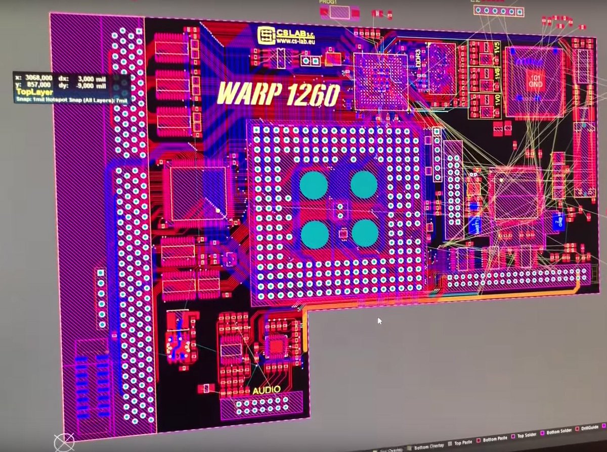
WARP 1260 accelerator board

Oh this looks and sounds sooo good: a new 68060 accelerator for Amiga 1200 is underway. And it has some awesome features.

https://pbs.twimg.com/media/DrE0XLFWsAAon3V.jpg

Wednesday, December 13, 2017

Building the TerribleFire TF530 accelerator board, part 5: Testing. More testing. And... happiness.

I'm learning new things about the TF530 almost daily...

Documentation is a problem when trying to build these accelerators: there's no place where you can quickly look up how to do something. Instead you have to dig through Stephen Leary's hour-long videos on YouTube, or a single endless thread on English Amiga Board, or ask in forums. Which is not a bad thing, but it's very inconvenient if you want to make progress. That's why I created some sort of "user manual" for the TerribleFire boards: https://amihelper.blogspot.de/p/terriblefire-accelerators.html

Anyway, what's happened since part 4 of this series?

Full setup with CF-adaptor and -card
Things were actually looking pretty good. I've been using a 24Mhz oscillator to build the board, and the original firmware (from a "rev. 2 final" GitHub checkout). But I wanted to rev up the board a little... Other people are using clockrates of 36, 40, or 50 Mhz. And then there are a couple of new revisions of the firmware. And in one or the other way these have to match. I've tried a 40MHz oscillator, and two other (apart from the original) versions of the firmware. Then there's the IDE controller. Simply plugging in an IDE cable - without any device attached! - changes the A500's behaviour in combination with the 40MHz oscillator. Exchanging the 1.3 Kickstart ROM for a 3.1 one made a difference once again. Lots of testing, and lots of glitches, and more testing, and more glitches: mousepointer uncontrollable, random crashes, boot picture gone, ...

It seems that the 33Mhz 68030 doesn't like overclocking very much - but with a 32MHz oscillator (33Mhz oscillators seem to be rare), it now runs stable! I expect a few more issues - like checking RAM soldering points - but for now I declare it "working fine". It boots quickly from the 512MB CompactFlash card attached, and with the additional 2MB of RAM on the TF530 and the new 3.1 Kickstart ROM the A500 is now an up-to-date, very usable Amiga!

Yesss! I am __very__ happy with it. :-)

SysInfo speed test with the 32MHz oscillator installed
Nice to have: an LED on the CF-card-adaptor

An "in progress" conclusion


From a personal perspective, I can say that I've learned a lot. I mean: A LOT. Stephen Leary's videos give a huge amount of information, and by building the accelerator I've expanded my set of tools, improved my soldering skills, and gained some knowledge about the parts used. Overall, for me it's a huge step forward in understanding the inner workings of Amiga computers, the TF530, and electronics in general.

And of course the Amiga 500 got a huge update, it's a completely different machine now. For a very reasonable (money-wise) price.

So the whole process is a massive success for me. :-)

No outside signs of the changes on the inside... :-)

Still, there are a few things to keep in mind about the TF530 accelerator and the build process: First of all it takes an insane amount of time to build, if you don't know what you're doing beforehand. I certainly didn't. There was a lot of research involved, on all levels. Secondly, the TF530 is clearly not an industrial-grade product: it's an "in progress" project, a moving target. You have several options when it comes to CPU and oscillator, and these have some interdependence with the firmware releases, which are still going on. The physical layout of the TF530 isn't perfect, you (may) need a relocator board to fit it into your Amiga, you (may) need to use specific connectors, and still it fits only barely between the Amigas other components and casing. For example, adding a Kickstart-switch may turn out to be quite difficult now with the TF530 in place.

But all these quirks don't change a simple fact:

It's effin' great! 
Awesome!
Amazing!
Magnifique!

Thank you, Mr. Stephen Leary!

Thank you very, very much for sharing,
and lighting up the TerribleFire!


So far, so good. I currently consider this to be the last entry in my little series about building the TerribleFire 530 accelerator board. But who knows. And there's so much more to do... maybe a TF328?

Overview and back catalogue of the series:
http://amigaalive.blogspot.de/p/hardware-building-terribefire-tf530.html

Saturday, October 28, 2017

Building the TerribleFire TF530 accelerator board, part 4: Software and Installation

Handling ~40GB of downloaded installation archives is not for the squeamish. And I built the M68000 CPU socket connector. And then there comes the moment of truth.

Disclaimer: This is not an instruction. Use at your own risk. No responsibility taken for whatever you do. Safety first. Kids, dont try this at home. 


That's what she looks after cleaning.

Now that I have a complete TF530, it's time to upload the firmware to the Xilinx CPLDs. Wow, Xilinx really offers a lot of software for download. (And US export regulations are weird.) Picking an older, smaller (3.5GB) version of Xilinx ISE for Linux from their website didn't work out, does not recognize my Diligent-based "Xilinx Platform Cable USB" JTAG interface. Trying Windows version, no success.

Nope, this one wouldn't do the job. Need more software.


Next Linux version (8.0GB) didn't work, too. Trying Windows version, no success. I've downloaded about 25GB so far... Well, long story short: A few days and a few more versions later, namely 14.6, there's a new button in Xilinx ISE's GUI: Diligent USB device. Yay. Finally. Job done, nerves wrecked.

Connecting the JTAG cable, and uploading the firmware then worked flawlessly.


Plug it in!


I'll be installing the TF530 into an Amiga 500. The TF530 has to be connected to the M68000 CPU socket on the mainboard. My first thoughts were to build something using wires, but that would leave the TF530 floating around the Amiga's casing, requiring some support. So I decided to go with the "68000 Relocator" board and build some connector from standard 2.54mm-grid pin headers soldered to it. The CPU socket on the mainboard is pretty flat, and it turns out that when using these pin headers you have to solder them to the "68000 Relocator" just at the tip, lifting up the board from the CPU socket as far as possible. And of course we don't want to damage the CPU socket by inserting wide pins into the very narrow CPU-pin slots, so the pin headers need some filing! Only next time I will do the filing before soldering the TF530 to the Relocator board, saves a lot of cleaning... But I'm quite pleased with the results, and it looks as if I can still - should I ever need to do so - put the M68000 CPU back into the socket and its pins will make proper contact.

Final step of installation is to connect the TF530's "A500" header to the Amiga 500's expansion port. "OVR" to pin 17, and "INT2" to pin 19. A small 2-pin header can (and probably should) be installed there, to be able to unplug the TF530 and the wires. I created it from two individual pins, because the distance between the soldering points on the mainboard is less than 2.54mm. Now that we have pin headers on both ends, a connector cable with two individual plugs on one end and a 2-pin-plug on the other, will certainly come in handy.

The INT2/OVR header, and building the connector cable.
What's left to do? Nothing!

Turn it on!


I have to admit this is quite a moment. I started this journey about nine months ago. This is the moment of truth. I'll have a bottle of cold beer ready to go. With a display and the PSU connected, I'm powering up the Amiga...

The TF530 fully installed. Will it work?

And...

...nothing. Black screen. No floppy clicks.

Maybe we should install some jumper at "CLOCKSEL".
Let's try again.

And...

https://www.youtube.com/watch?v=QuoKNZjr8_U


 ...it's alive!


Now where's that bottle of beer?


Next time we'll see how she really does - watch out for part 5 of our series "Building the TerribleFire TF530 accelerator board"!


Overview and back catalogue of the series:
http://amigaalive.blogspot.de/p/hardware-building-terribefire-tf530.html

Saturday, September 16, 2017

Building the TerribleFire TF530 accelerator board, part 3: Parts inspection, and soldering

Let's see what we've got. And how we're gonna put it together. This one had a little surprise for me.

Disclaimer: This is not an instruction. Use at your own risk. No responsibility taken for whatever you do. Safety first. Kids, dont try this at home. 

Parts and BOM, and the shiny blue PCB.
It looks like I haven't missed much so far. Everything required to populate the board is there (except for the CPU socket connector, for which some substitute will be built), and I'm still able to identify the individual components! :-)

Parts and tools.
So, with Stephen Leary's instructional video (see below) on my computer's screen, I started soldering. May I note that not only does his video provide helpful and important information and hints, but also is a pleasant accompaniment when working on the TF530.

Soldering the first SMD chip on to the board quickly resulted in the chip being roasted, and the PCB damaged. Lol. Surprise. It turned out to be waaaaaay more difficult than I had expected.

Working with tiny SMD components poses some unexpected problems. For example if you're used to soldering hole-though parts you will most likely use way too much solder on your first attempts. Well, I did. Then, when you got used to using really very little solder, you find out that you cannot easily suck away the solder if you've made a mistake, because the amount of solder is too little for the desoldering pump to work on. Then you may learn the painful way that tiny PCB chip pins are reeaaally weak, you have to treat them really gently. And finally, when checking results of your soldering, you may find out that your grandma's magnifying glass does what it's supposed to do - to magnify - but it's scratched or unclear, and really creates more confusion than it does help.

First chip in place. Dirty, but undamaged!
But after some practicing with the damaged board and chip, things looked better. I learned to use the right amount of solder, the right amount of soldering flux, and to move the soldering iron at the right speed, and started working on a new board - with far better results.

More components.
After some hours of focused soldering and (visual) checking it looks as if my first TF530 might soon be ready for testing.

TF530r2 fully populated!
She's currently no beauty and needs some serious cleaning, but she makes her owner very proud. :-)

If you wanna try to build one, here's Stephen Leary's first "how to" video (we're still waiting for the second):

https://www.youtube.com/watch?v=xG_5oDeLdGE

Next time we need to find out if she's alive - watch out for part 4 of our series "Building the TerribleFire TF530 accelerator board"!

Overview and back catalogue of the series:
http://amigaalive.blogspot.de/p/hardware-building-terribefire-tf530.html

Thursday, August 3, 2017

BANG! There it is: Vampire V4 standalone & Vampire V4 Amiga 1200

And this is how things happen. You have an Apollo team, and a Vampire team, and Kipper2k and Majsta and all the others, and they just go the way, all the way.

Today has been announced Vampire V4, and what a beast it is: it comes in different flavours, including an Amiga 1200 version, and a standalone version.

Among it's features are the Altera Cyclone V A5 FPGA, 512MB DDR3 RAM, FastIDE with two connectors (40 and 44-pin), HDMI* video out, dual Kickstart-flashrom, USB, ethernet, and MicroSD storage. Additionally, the standalone version will feature two DB9 mouse/joystick ports.

From the official announcement: "The Vampire V4 standalone system will be a complete new Amiga system powered by the 68080 CPU core and the complete SAGA chipset (AGA compatible)."

Probably most interesting are three I/O ports on the new Vampire V4. Currently we have no information about these, but could this be the basis for a new standard of Amiga expansion devices? Will this be what people build upon, and make the Vampire V4 the new Amiga?

It has to be said, though, that there's some sort of question mark regarding the Amiga 600 version of the Vampire boards. The announcement of the V4 says "Amiga 600 with kippa’s adapter (if produced)", and assuming that "kippa" is "kipper2k", things don't look too well: recently, kipper2k left a note on his website (see sources, below) that he doesn't intend to continue making the Vampire 600 boards. Let's just hope this doesn't affect the overall roadmap of the Vampire boards, and that someone will build the adapter for the V4 600.

Anyway, exciting times we live in!

Congratulations!
  
http://www.apollo-accelerators.com/images/v4.jpg


*) probably, see sources below

Sources: 
http://amiga-news.de/de/news/AN-2017-08-00003-DE.html
http://www.apollo-accelerators.com/files/V4_announcement_v1_5.pdf
http://forum.apollo-accelerators.com/viewtopic.php?f=8&t=1804
http://kipper2k.com

Wednesday, July 26, 2017

Building the TerribleFire TF530r2, Part 2: Obtaining the components

So I've made the descision to try to build a TerribleFire TF530r2 accelerator. The TF530 uses SMD components, which are really small, but the overall number of components is quite low. Based on that, I decided that with good eyesight and accepting some fail-rate it should generally be possible to build the thing.

Disclaimer: This is not an instruction. Use at your own risk. No responsibility taken for whatever you do. Safety first. Kids, dont try this at home. 

Parts and cost


As we know, the docs of the TF530 can be found at: https://github.com/terriblefire/tf530

The readme file contains a BOM (bill of material), of which columns 2 to 4 are relvant for component indentification. It takes some time to get used to specifications and naming. When looking for parts, keep an eye on the "Package" (column 4 of BOM), which in some cases describes the required type (shape/layout/...). Also sometimes you will find out there are variations of components, like for industrial use, made of different material, etc., which are identified by some suffix appended to the name given in the BOM. Finding the matching socket for the 68030 CPU can also be a bit tedious, it has a special layout.

And of course there's the PCB (circuit board) itself, which you can order from dirtypcbs.com: http://dirtypcbs.com/store/details/1330/tf530-rev2b-zip

After hours of searching the internet, I got this impression:
- the PCBs are really cheap
- parts are generally available
- some parts seem to be a bit rare and can only be ordered from one or two retailers
- few parts are cost relevant: CPU, FPU, sockets for CPU and FPU, and SRAM
- the socket / connector to the Amiga's original CPU socket is a critical part that's rare, thus comparably expensive

I decided to go with a 33MHz 68030RP CPU, 40MHz 68882 FPU, and will not use industrial parts, which cost more and are probably more reliable, but I'm assuming there are no extreme temperatures etc. on the TF530. For the 68000-socket connector I'll try to modifiy some other pin connector (2.54mm pin grid).

It turns out that including shipment from different retailers we're still in the "around 100EUR" range for a complete accelerator board, which is an acceptable risk.

So I placed my orders.

Sources


TF530r2 PCB (circuit board) from dirtypcbs.com:
http://dirtypcbs.com/store/details/1330/tf530-rev2b-zip
You probably want to order a "Protopack (+/-10)" which is the cheapest option, and gives you (about? +/-?) 10 boards to play with.

I ordered most of the parts for the TF530r2 from these retailers:
http://www.tme-germany.de
http://www.reichelt.de
http://www.darisus.de
http://www.conrad.de
http://www.mouser.de

68030 CPUs and 68881 or 68882 FPUs are available on eBay.

Additionally, I ordered one or two individual parts via eBay directly from China if there was a good offer.

Special thanks to the very friendly and helpful guy at CONRAD store (Munich, Moosach) who recommended to buy a soldering station and gave lots of information, you're doing a fantastic job! 


Delivery & Conclusion


The overall time spent on obtaining the parts has to be somewhere around 20hrs, for research, talk, orders, and purchases at local stores. 10 weeks went by from placing the first order to receiving the last one.

Everything arrived properly packaged, and hopefully it's the correct parts... I'll just have to trust them on this. ;-)

Blue TF530r2 PCBs look great, my "protopack (+/-10)" contained ten pieces. On first visual inspection one of them that has a tiny flaw between two IC soldering pads - maybe that's the "Protopack (+/-10)" option? Less quality control than ordering "10" (pieces)? I'll be using that flawed one for some SMD-soldering warm-up practice.

Overall I had one or two issues with the ordering process, but I'm pleasantly surprised how well everything worked, including resolving these issues.

Next time we'll see what we've missed so far, and be doing our first soldering tests - watch out for part 3 of our series "Building the TerribleFire TF530 accelerator board"!

Overview and back catalogue of the series:
http://amigaalive.blogspot.de/p/hardware-building-terribefire-tf530.html

Sunday, July 16, 2017

AMIGA alive 02: M-Tec Mastercard SCSI controller installation (Video)

"AMIGA alive 02 - M-Tec Mastercard SCSI installation" is out! This time we're installing a SCSI controller into our Amiga 1200. Hope you enjoy it, and as always comments are welcome!


https://www.youtube.com/watch?v=OpAuV6Vdl-I


Wednesday, May 31, 2017

Building the TerribleFire TF530 accelerator board, part 1: Introduction

Stephen Leary's TF530 accelerator board for the Amiga 500 is a nice piece of hardware for several reasons. It's low-cost, open-source, fast, has an IDE controller, and a great name.

Why not build one youself?

Disclaimer: This is not an instruction. Use at your own risk. No responsibility taken for whatever you do. Safety first. Kids, dont try this at home. 

You need some proper tools, and should have some good soldering experience - SMD parts are really small... And you need some patience and knowledge to find the components.

For starters, check the video below, where Stephen shows the first steps in building it "from scratch".

"TFV#45 - Building Your Own 68030 Amiga 500 Accelerator - SMD Components"


https://www.youtube.com/watch?v=xG_5oDeLdGE

Find basic information, PCB layout, bill-of-material and software on Stephen's github account:
https://github.com/terriblefire/tf530

(Note: Stephen is still working the board, releasing updated revisions. Make sure you check board revisions, bill-of-material, and information accordingly.)

Also keep an eye on his YouTube channel, he releases new videos quite often, giving updates on his developments, explaining details of his boards, or even reviewing user boards:
https://www.youtube.com/channel/UCu4uiUtALy1ILAxNh7TGsmQ

If you need more information, you should watch Stephen's videos, and get in contact with other users via the "Terrible Fire Accelerators" thread on EAB / "English Amiga Board":
http://eab.abime.net/showthread.php?t=85380

Now let's see if we can build the TF530 - watch out for part 2 of our series "Building the TerribleFire TF530 accelerator board"!


Overview and back catalogue of the series:
http://amigaalive.blogspot.de/p/hardware-building-terribefire-tf530.html 


Amiga Kit (GB) and Relec (CH) to retail Apollo / Vampire accelerators

The next step in Apollo / Vampire accelerators development: After the boards have been put into mass production, they're now available from Amiga retailers AmigaKit in Great Britian and Relec in Switzerland!


http://www.amigakit.com

http://www.relec.ch
http://apollo-accelerators.com/images/v500v2.gif

AmigaKit reports that the first batch of Vampire 500 V2's has sold out in just hours - be quick to place your order!

http://apollo-accelerators.com/images/V2-128.png


You can read AmigaKit's news release here:
http://www.amigakit.com/news/News_Release_Apollo_Accelerators.pdf

Your can read Relec's news release here:
http://relec.ch/frch/index.php?option=com_content&view=article&id=141:vampire-qon-the-roadq&catid=1:relec&Itemid=8&lang=en


Home of the Apollo accelerator boards:
http://apollo-accelerators.com

Sources:
http://relec.ch/frch/index.php?option=com_content&view=article&id=141:vampire-qon-the-roadq&catid=1:relec&Itemid=8&lang=en
http://www.amigakit.com/news/News_Release_Apollo_Accelerators.pdf

Wednesday, May 3, 2017

Help! Microbotics / Paravision M1230XA accelerator board repair

*****************
UPDATE 2018-02-17:
Yesss, it works again. Another gem saved. Microbotics' "MBRTest-2" tool from the M1230XA install disk does an excellent job of testing (any) RAM. FastRAM installed on the M1230XA can be tested even without adding it to the system. That way I was able to diagnose the problem, and fix it (see picture below: green wire fixes some broken address- or data line). The board also got some new capacitors.


Thanks to everyone who helped me! :-)

*****************


I have an old Microbotics / Paravision M1230XA accelerator board, and it's not working properly. Can you help me debugging it?

For starters, a few screenshots would help: SetXA utility window / running, Early Startup Menu boards listing, "showconfig" output, SysInfo screen with speed test results (each of course with a working M1230XA installed).

I mostly test my board with Kickstart 3.0 - are you aware of any issues regarding KS3.0 and the M1230XA?
(apart from the fact that RAM has to be added "manually" / software-wise)


Please leave a comment in the comments section below, if you think you can help.

Or contact me via amiga.org

Or via amigaworld.net


If you want to keep track of my efforts debugging/repairing the M1230XA it's maybe best to watch my "Microbotics / Paravision M1230XA accelerator board information" page.


Thanks!

- - -

Situation / Error description:

The Microbotics M1230XA seems to work fine without memory installed.

With memory installed, adding the memory to the system doesnt work.

This is the situation with a Kickstart 3.0 Amiga 1200:
In the picture below you can see the previous settings ("RAM Speed: 100nsec", ...), new settings("setxa ramspeed 70", ...), and the state after adding the board's memory. After "setxa addmem", it takes maybe half a second to activate the memory. During this short timespan the Amiga remains usable - e.g. a mouseclick on the workbench. But once the memory has been added, it looks like any memory access fails. That includes (re)focussing the shell-window, clicking an icon. When keeping the shell window active (no workbench click), keyboard input is still possible, but entering a valid command and hitting <Return> crashes the machine.


Behaviour is almost the same with different RAM SIMMs/speeds/cycles, only the type of system crash differs: sometimes screen graphics corruption, sometimes black screen, sometimes Guru Meditation.

With a Kickstart 3.1 (=autoconfiguring) Amiga 1200 the screen stays black on powerup.

Wednesday, April 12, 2017

Accelerators galore

In recent times, a lot of new hardware developments for retro computers are popping up. Among these are a remarkable number of different accelerators for the Amiga 500, 600, and 1200 - here's an overview of what's currently available and/or in development.

Please note that information provided here may not be 100% complete. Read about the boards' details on the websites provided, or get in contact with the developers, if in doubt.

Have fun choosing your next-gen Amiga accelerator!

ACA500plus

Individual Computers brings us this accelerator board for the Amiga 500, with some interesting features - like e.g. built in Kickstart ROMs, AmigaOS 3.1 installer software, and a connector for A1200 accelerators.

CPU: MC68EC000 at 14 to 42MHz
8MByte RAM
8MByte FlashROM
two CF-card slots
Action Replay-compatible freezer
7-segment display "DisMo"
Kickstart V1.2, V1.3 and V3.1, and AmigaOS 3.1 installer in FlashROM
Extension connectors: A1200-compatible Clockport, local 16-Bit extension port, connector for A1200 accelerators

Website(s):
https://icomp.de/shop-icomp/de/shop/product/ACA500plus.html

ACA1221ec

Individual Computers' low-budget accelerator for the Amiga 1200, sells for only about 120 Euros.

CPU: 68EC020
17 to 42 MHz
16MB RAM, 9MB of which are usable FastRAM
1MB-MapROM option
2 clockports, one of which is hi-speed (for RapidRoad USB host controller use)

Website(s):
https://icomp.de/shop-icomp/de/shop/product/aca1221ec.html

ACA1233n-40 and ACA1233-55

Individual Computers' 68030 accelerators are still available.

CPU: 68030 at 40 or 55 MHz
128MB RAM
MapROM option
Clock port

Website(s):
https://icomp.de/shop-icomp/en/produkt-details/product/ACA12xx.html

Furia EC020 for Amiga 600

On sale for quite some time now are the Furia accelerators for the Amiga 600, available via online stores (e.g. http://vesalia.de or http://lotharek.pl )

CPU: 68EC020 at 33MHz
FPU: 68882 (if present) 
9.5MB FastRAM 
Maprom function

Website(s):
http://www.kuchinka.cz/furia/

TerribleFire TF520, TF530, and TF540

Stephen Leary's open-source DIY accelerators for the Amiga 500. Documentation on how to build the 68020 and 68030 CPU versions (TF520, TF530) are already available via GitHub and YouTube (see links below), and just recently Stephen has begun developing the 68040 version (TF540).

CPU: 68020, 68030, or 68040
FPU: 68881
IDE controller

Here's a demo of the TF530 in action, comparing a stock A500's performance to that of a TF530-equipped one, using "Frontier - Elite II":

https://www.youtube.com/watch?v=XRO9j2G9owc

Website(s):
https://www.youtube.com/c/TerribleFire
https://twitter.com/terriblefire

https://github.com/terriblefire/tf520
https://github.com/terriblefire/tf530

Wicher 500i

Accelerator board for the Amiga 500, from Poland.

CPU: MC68000/68010
Max. clock: 50MHz
RAM: 1-8 MB SIMM 72 (FPM,EDO)
IDE Controller
SPI Controller

Here you can see it in action:
https://youtu.be/WWG1BVmYEXU
https://www.youtube.com/watch?v=A6-r4OQP9Sc

There's also a Wicher 2000 accelerator board for the Amiga 2000 planned.

Website(s):
http://retro.7-bit.pl

HC508

Homebrew accelerator for the Amiga 500 by blogspot/YouTube user "m68k". Not much is known about this one, especially if it'll be sold to the public or made open-source one day.

68HC000 CPU at 50 MHz, 100% MC68000 compatible
IDE-controller (40-pin) for HD and CD-ROM
integrated CF-Card slot
8 MB FastRAM (1 wait state)
512k FlashROM for Kickstart (1 wait state)
Utility to individually (de)activate any module (CPU, RAM, ROM, IDE)

Here you can see it in action:
https://www.youtube.com/watch?v=VK1h65u8UIU

Website(s):
http://amigaprj.blogspot.de

Vampire 500 V2 and Vampire 600 V2

FPGA-based accelerators - and much more - for the Amiga 500 and 600. Amiga 1200 version is in development. CPU performance far beyond that of a 68060, SAGA graphics with Full-HD resolution, HDMI output, 128MB RAM, MicroSD card slot, IDE controller (Vampire 500 only). The ultimate boost in performance!

Website(s):
http://apollo-accelerators.com